

Why solar starts at the design stage
Good solar integration begins at the concept stage. By treating the roof as a functional energy asset rather than just a weather shield, architects can blend architectural form with engineering function.
Whether you're designing for immediate installation or preparing buildings to be solar-ready, early engagement with specialist solar designers ensures better outcomes for your clients and your projects.
Enhancing value through simplified form
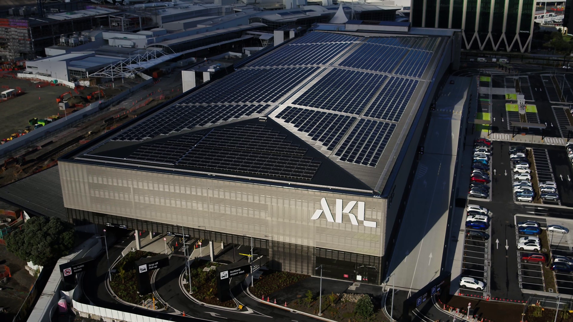
The form and layout of the roof have the single greatest impact on a PV system's potential. We see many designs featuring complex, fractured roofscapes that force PV arrays to be split into small, inefficient sub-groups.
- Simplify the geometry: Aim for large, uninterrupted roof planes. Complex angles and hips reduce usable space and complicate installation.
- Form follows function: Prioritise a roof design that optimises solar access. A simplified roof form not only maximises energy yield but often results in a cleaner, more deliberate architectural aesthetic when panels are installed.
- Avoid fragmentation: Ideally, arrays should be grouped together rather than scattered. Fragmented or irregular roof shapes often force the use of smaller sub-arrays, which increases installation complexity and costs while reducing the available generation yield. Continuous, symmetrical configurations generally provide a more pleasing architectural appearance.
Orientation and yield
While true north is the standard for maximum total energy generation, modern usage patterns allow for flexibility in orientation.
- North facing: Ideal for maximising specific yield (total kWh generated per kWp installed).
- East/west split: Arrays facing east and west are viable and often beneficial. While they may generate slightly less total energy than north-facing arrays, they produce power earlier in the morning and later in the afternoon, better matching the peak consumption periods of residential and commercial buildings.
Tilt angles and self-cleaning
The angle of the array impacts both energy production and long-term maintenance.
- Ideal pitch: For pitched roofs in New Zealand, a pitch of 20° to 30° is near optimal for year-round generation.
- The 10° rule: A minimum tilt of 10° is recommended to ensure panels self-clean via rainfall. Arrays flatter than 10° accumulate dirt and lichen more quickly, significantly reducing performance and increasing maintenance costs.
- Commercial flat roofs: On large flat roofs, a 10° tilt strikes the best compromise. This angle minimises inter-row shading to maximise total roof yield. Steeper tilts improve per-panel generation but significantly increase wind loading, often requiring expensive roof strengthening.
Managing shadows
Shading is the enemy of solar performance. Because PV modules are connected in series strings, shading on a single panel can disproportionately reduce the output of the entire array. Localised shading on single cells can create hot spots that lead to accelerated degradation, resulting in long-term failures and safety issues.
- The "keep clear" zone: Design the roof to avoid structures or equipment that cast shadows on north-facing surfaces.
- Vertical obstructions: Be mindful of parapets, chimneys, lift overruns, satellite dishes and flues. Even thin shadows during peak sunlight hours (9am–3pm) can dramatically reduce system performance.
- Vegetation: Consider the mature height of landscaping and trees to ensure long-term solar access.
Aesthetics and integration
A well-integrated system looks intentional.
- Flush mounting: For pitched roofs, flush-mounted arrays generally detract less from the building's appearance than tilted frames and experience lower wind loading.
- DC cable routing & safety: High-voltage DC solar cabling presents a specific fire risk due to arcing. We recommend routing DC cables externally to keep this risk outside the building envelope and facilitate maintenance — using UV-resistant conduits or aluminium cable tray with a lid, along routes that follow natural building lines or are screened from view.
- Inverter placement: Inverters require a cool, secure and accessible location. They can produce operational noise, so position them away from primary living areas or quiet zones, and protect them from direct sunlight.
- Reflectivity: PV panels have an anti-reflective coating and are less reflective than glass or some roof finishes. For sensitive locations, orientation and tilt may need adjusting to manage glint and glare.
Maintenance and safety
PV arrays are durable assets that will occupy the roof for 30 years or more, requiring long-term structural and maintenance planning.
- Safe access: Include safe access points for installers and maintenance personnel. Panels should be spaced away from the roof edge.
- Walkways: Avoid designing a "sea of glass." Arrays should be separated into sub-groups (no more than 3 modules deep) with walkways (>0.5m) between them to allow for cleaning and maintenance access.
- Drainage: Ensure the array layout does not impede natural drainage channels or gutters.
- Fall arrest design: Fall arrest systems are frequently overlooked in early planning. Integrating these systems with the PV design avoids late-stage conflicts.
- Skylights: Avoid placing panels over skylights. If the skylight is not trafficable, allow a walkway between the skylight and PV panel.
Structural considerations
Solar arrays introduce additional static and dynamic loads that must be integrated into the primary structural design.
- Load capacity: The roof structure must accommodate the dead weight of the PV system (typically 10–20 kg/m²) alongside expected seismic loads.
- Wind loads: The PV array may also increase wind loading, changing a distributed load into point loads where fixings attach to the roof structure or cladding.
- Corner zones: On larger buildings in high wind zones, corner and edge zones experience the highest wind pressures, often making the required structural reinforcement uneconomical for PV.
- Fixing and warranties: Mechanically fixed systems typically require roof penetrations, which can increase the risk of leaks and void warranties. Always confirm with the roofing manufacturer that the mounting system is compatible with their product.
Future-proofing: solar-ready design
If budget constraints prevent immediate PV installation, a solar-ready design minimises future costs and disruption.
- Pre-wiring: Install conduit runs from the roof to the main switchboard location during construction.
- Space allocation: Designate wall space for future inverters and battery storage near the distribution board.
- Structural provision: Engineer the roof structure to accommodate the future load of solar panels now, avoiding prohibitive remedial reinforcement later.
Need expert advice on your next project? Revolve Energy partners with architects to model, design and specify high-performance solar systems that respect your architectural vision.